Adjustment methods for brightness and color of LED display screens
At present, the production and manufacturing quantity of dual color light-emitting diode (LED) display screens is relatively large, and their technology is also relatively mature. The structure and principle of display screens manufactured by various enterprises are basically similar, and some specialize in producing display multimedia cards. Therefore, improving the technical performance of display screens and reducing costs are the key to competition among various enterprises. Nowadays, the prices of LED display screens sold in the market are basically the same. However, the quality of display screens produced by different enterprises varies due to various reasons, mainly including:
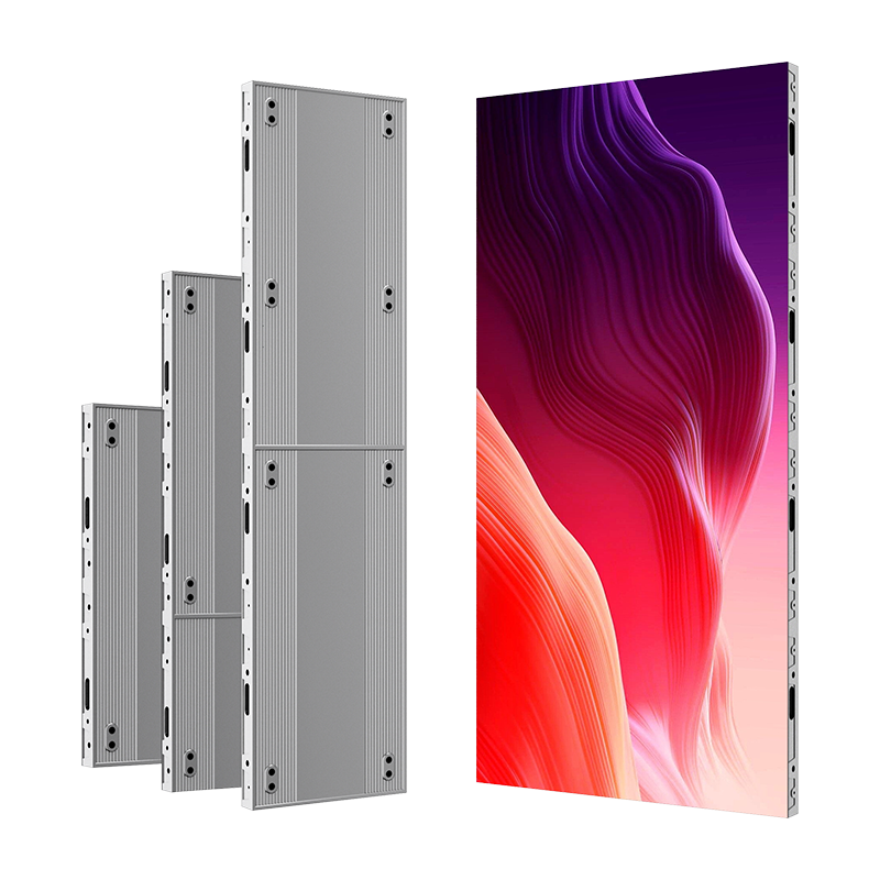
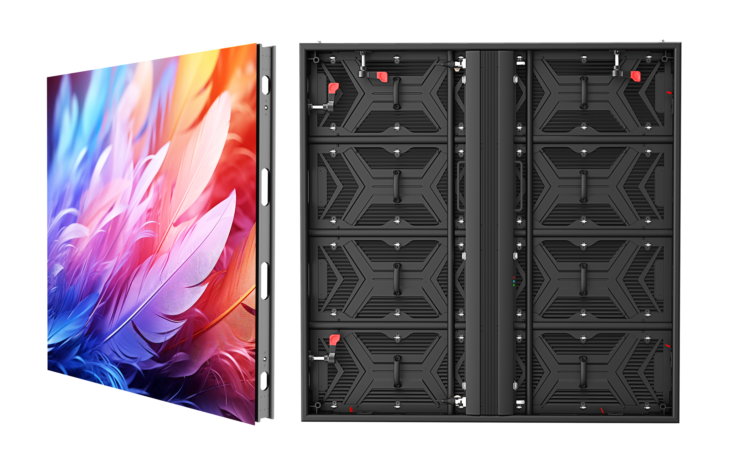
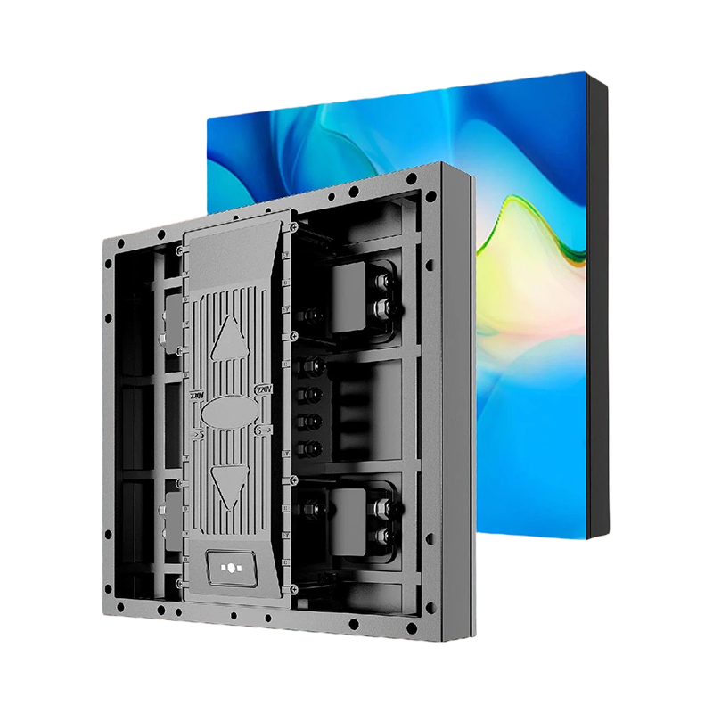
① The quality, brightness, brightness uniformity, packaging and other technologies of LED display modules;
② The communication transmission method and anti-interference ability of data;
③ Display multi-point adjustment of scanning circuit current and control the current at each point. A display screen that has undergone multi-point adjustment not only has good uniformity, but also displays images with better brightness and color effects. The dedicated display scanning circuit has good display effects, but the price is relatively expensive.
Nowadays, LED display screens sold in the market are produced by many companies using the same design technology, methods, and display modules, but their performance differences are quite significant. The different color ratios result in significant differences in image effects; The scanning frequency and operating current of the module not only affect brightness, but also involve issues such as service life. Therefore, correctly determining various technical parameters is the key to manufacturing display screens, and can also be said to be a reflection of display screen technology experience.
2 Display scanning principle
The control structure of LED display screens manufactured by different enterprises varies, but the display scanning circuit of the display screen is basically the same. The display scanning circuit of the dual color LED display screen is shown in Figure 1. In Figure 1, IC1 and IC2 are data latch circuits 74HC595, which respectively latch red and green data. Their performance is:
① Serial input with 8-bit parallel output;
② Data locking and data clearing functions;
③ The output has strong driving capability. Resistors RPB1 and RPB2 are current limiting resistors, and their values are selected based on color and module brightness. ML1 is a dual color LED display module with a total of 64 LEDs in 8 rows and 8 columns. Among them, 8 pins are red signal input terminals, 8 pins are green signal input terminals, and 8 pins are row control input terminals. There are a total of 24 pins. Transistors Q0, Q2,... Q7 are used for row gating and driving. IC3 is a 3-8 address decoding circuit 74HC138, with 8 gate outputs controlling the corresponding rows. The circuit in the diagram is the principle circuit of the display screen, and its data transmission method is asynchronous with the row signal. Firstly, 8-bit red and green color data are simultaneously transmitted to circuits IC1 and IC2 and the data is latched. Then, a row control signal is transmitted to light up a row of LEDs. The above operation is repeated, except that the row signal moves to the next row and continues until the eighth row, which is a complete scanning process.